


How To Install A Condensate Drain
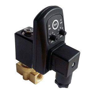
Figure 1: Condensate drain valve installation
A condensate drain valve is used to drain condensate from process lines or storage tanks. They assist in supplying clean and dry compressed air to the system. So, its installation should be carried out with high importance. The same principles apply for electronic and timer condensate drain valves.
In short, a condensate drain works by collecting built-up condensate that flows through the drain line and into the drain pan. For electronic condensate drains, a sensor detects the level of condensate and signals the electronic control once it exceeds the set level. The valve is then actuated to open the outlet in the drain line, discharging the condensate. The valve closes once sensor detects the the drain pan is almost empty. A timer condensate drain works on the same principle, but instead of a sensor it has a timer for being open and closed. Read our article on condensate drain valves for more product information.
Table of contents
Check out our condensate drain selection!
Installation basics
The proper installation of the condensate drain enhances the operation of the compressed air system. Therefore, the basic guidelines that should be considered are:
- Ensure that the maximum operating pressure is within specification.
- The valve must be installed upright with no tilt.
- The drain line must be fitted securely to prevent a pressure loss in the line.
Drain line installation
The drain line should be installed below the lowest point of collection in the compressed air system for efficient drainage and to prevent the accumulation of condensate. Figure 2 shows the interpretation of an inaccurate (left) and accurate (right) way of installing the drain line. This installation utilizes an air equalization line, but this is only needed in certain applications.
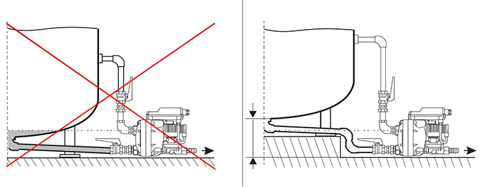
Figure 2: Inaccurate (left) and accurate (right) way of installing the drain line. Installation height for a condensate drain is at the lowest point in the system
Slope
Install on a downward slope
The drain line must be installed to have a continuous downward slope for proper drainage as shown in Figure 3.
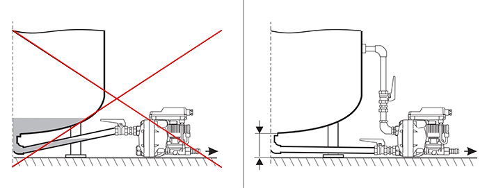
Figure 3: Incorrect (left) and correct (right) slopes for drainage. Drain line installation should have a downward slope.
Water pocket
Water pockets should be avoided as much as possible when installing a supply line. An example of a water pocket is shown on Figure 4.
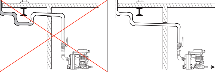
Figure 4: Installation of drain line to avoid water pocket
Avoid upward slope and water pocket if the pressure hose is directly installed as an inlet. In case the slope of the drain line is not sufficient due to the high rate of condensation, a ventilation line should be added.
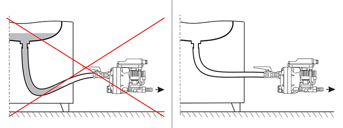
Figure 5: Installing the pressure line directly as an inlet
Pressure
The condensate line should be able to drain the condensate properly with the operating pressure of the system. For more than one source, the condensate must be drained separately for each source.
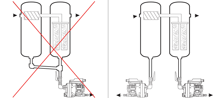
Figure 6: The condensate must be drained separately for each source in the case of multiple sources.
Electrical installation
It is important to look at the manual of your specific product for correct electrical wiring information. All of the relevant national and international safety regulations and codes (such as IEC 60364) should be followed during the electrical installation and must be performed by qualified personnel.
- Refer to the connection diagram in the manual for installing the cables and wires.
- The system power supply must be deactivated before installation or maintenance.
- For power supply requirements, make sure the input voltage is within the permissible limit.
- If the voltage is carried by potential-free contact, it requires an accessible separator like a plug or switch nearby to disconnect the electrical power.
- The terminal for the potential free contact and external test should be assigned and connected according to the installation guideline.
Control unit
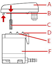
Figure 7: Control unit installation: Control unit (A), hook (B), sensor (C), contact springs (D), sealing mat (E), & service unit (F)
Electronic level controlled condensate drains have control units. They have the controls and sensors housed in it. The service unit contains all of the wear components for the condensate drain. Therefore, these two units can be separated if maintenance, repairs, or replacements are needed. Ensure the system is deactivated to perform maintenance and installation work when the control unit is opened. Following are some basic steps for installation of the control unit:
- If obtaining a new service unit, ensure it is compatible with the control unit.
- Inspect the units for any impurities, mostly the sealing mat and contact springs.
- Properly locate the sensor into the service unit. The arrow on the right shows the locating point on the control unit.
- Attach the control and service unit back together. The arrow on the left shows the mounting point.